
Dankubator Instructions
This is a work in progress. I wanted to get something up asap for anyone who is confident without more details. I will refine this in the coming weeks to have more details, photos, videos, etc.
(Scroll down for photos)
Overview
The overall process is something like this:
- Cut holes in a food grade hot box
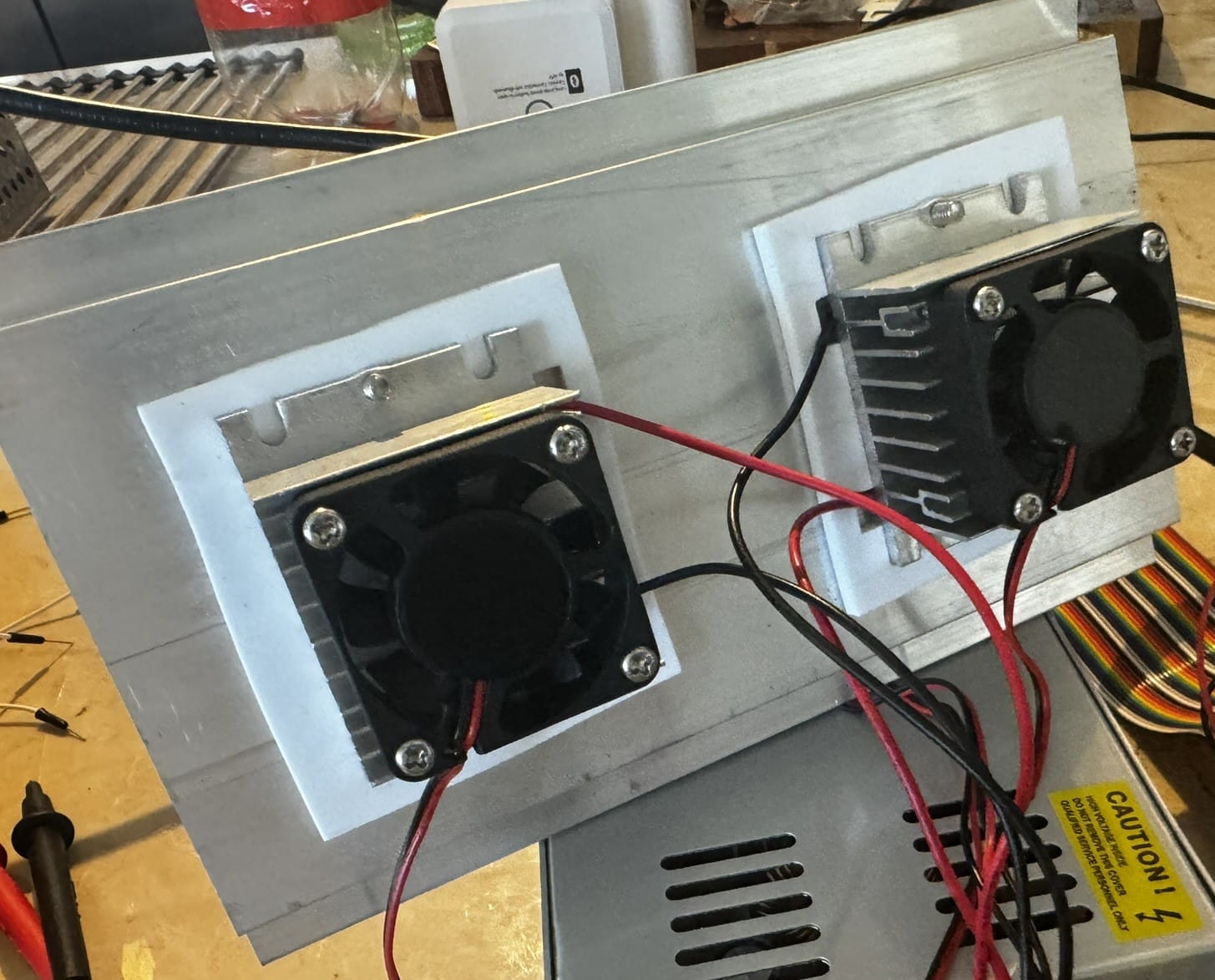
- Attach a thermoelectric (peltier) cooler through some of the holes
- Attach an outtake fan on one of the holes
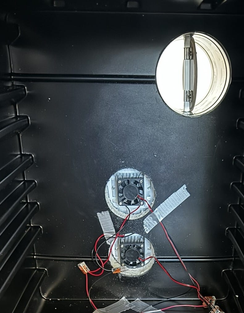
- Attach a damper on the intake vent (I will probably add one to outtake soon)
- Run wiring through one of the holes to connect to these components inside of the box
- The cooler and cold sink fans
- A circulation fan
- A temp/rh sensor (sht30)
- A temp/rh/pressure sensor (bme280)
- Then, outside of the box
- Connect a 12v power supply to a 5v buck converter
- Power a raspberry pi with the 5v
- Run the 12 and ground to components
- Share ground between 5v and 12v circuits
- Install the code on the pi (It is in a private GitHub repo I will make public once I figure out which account to use.)
Parts List
You can find the parts list on this post.
Tools
- 3-inch hole saw
- 4-inch hole saw
- Screwdriver
- Drill
- M4 Screws
Step by Step
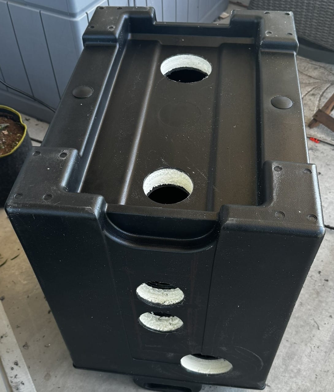
Cut holes in the container
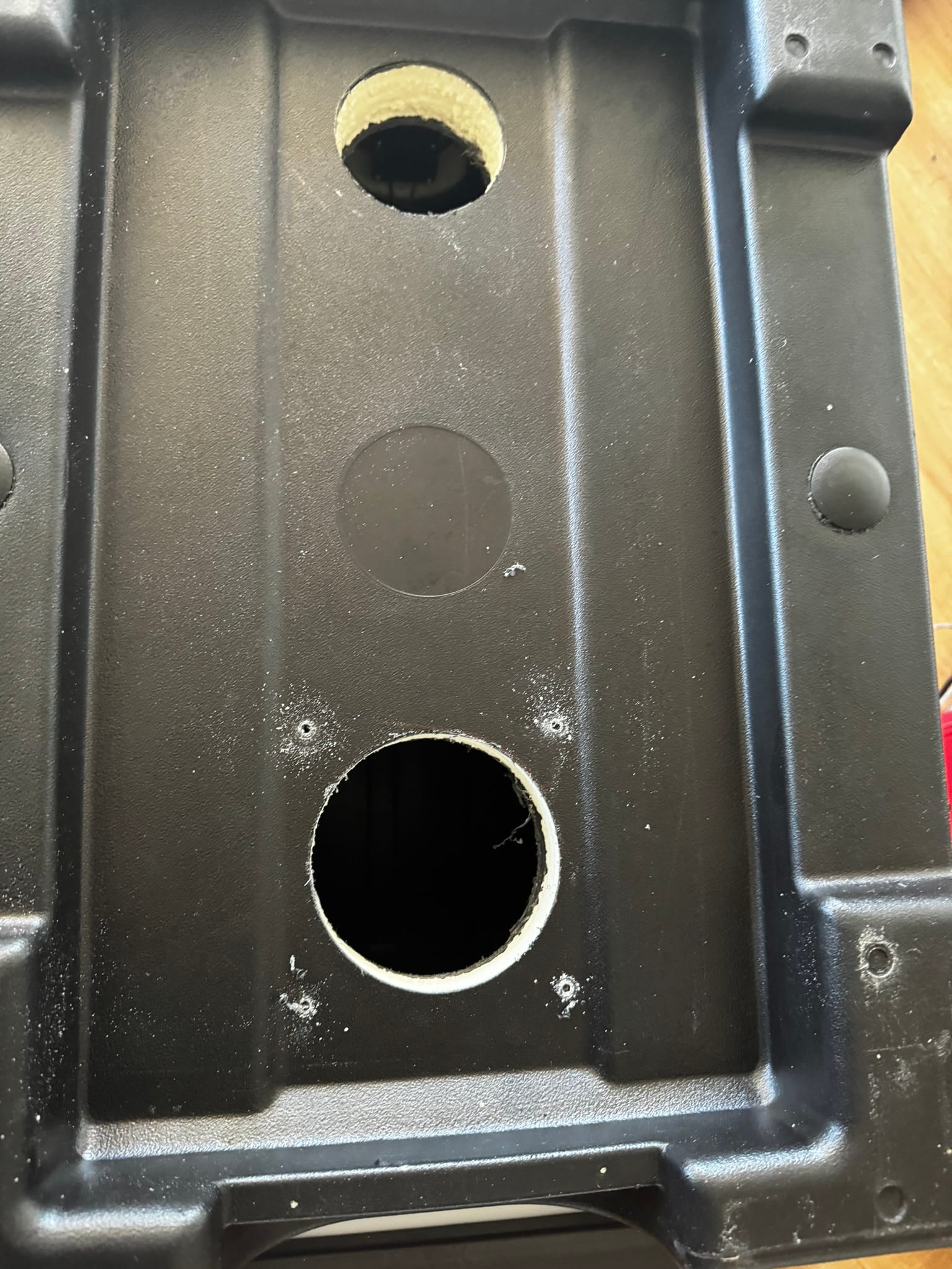
First, the bottom of the container
- 4-inch hole, towards the front, will be the air outtake vent
- 3-inch hole, towards the back, will be where we run the wires in
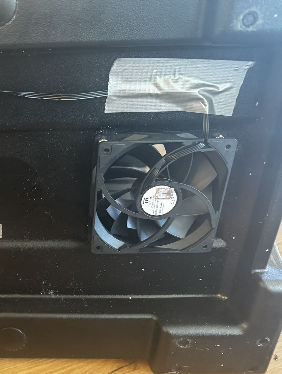
- Also, drill four pilot holes for mounting a 120mm fan on the 4-inch hole
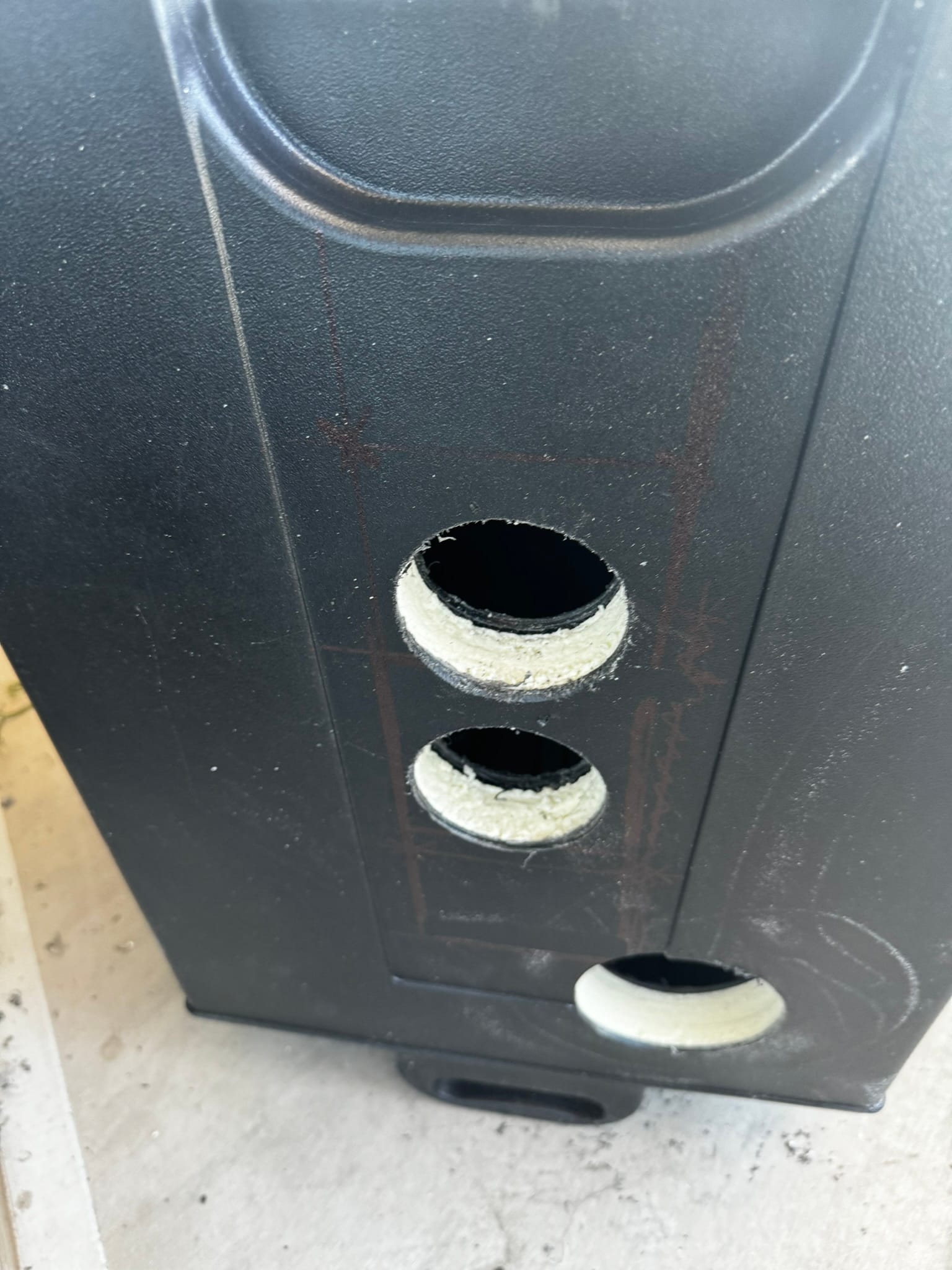
Next, the back of the container
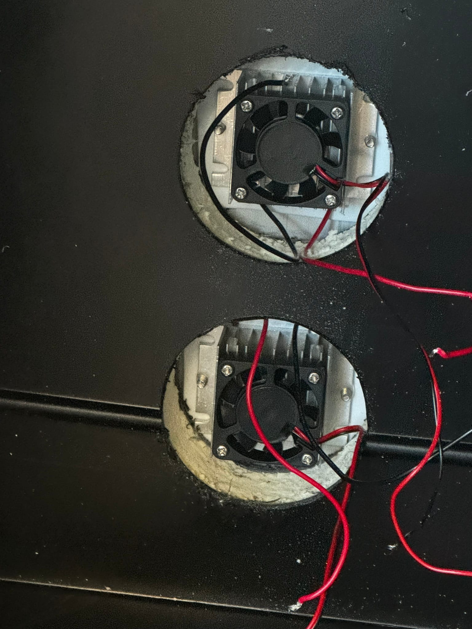
- Two 3-inch holes in the middle
- 4-inch hole near the top left
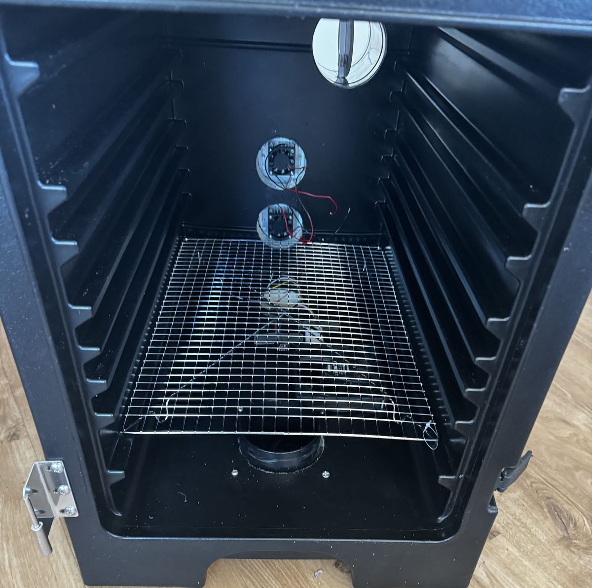
Now we can attach the components to the Dankubator
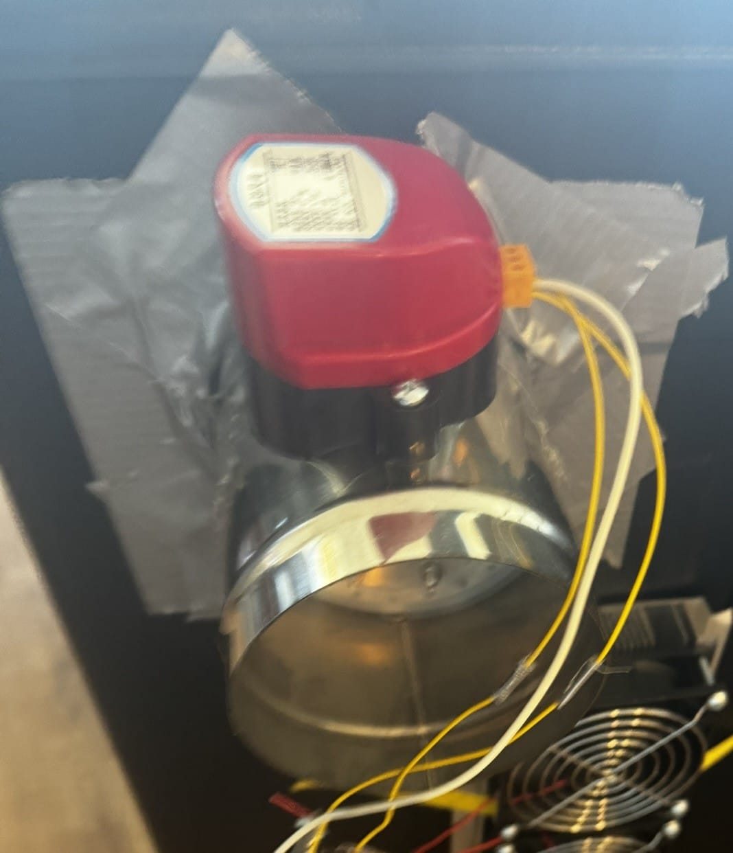
- Attach the cooler module and the damper to the holes on the back of the box.
- Secure the cooler by screwing a simple strap over it.
- Secure the damper with duct tape. Could also use glue.
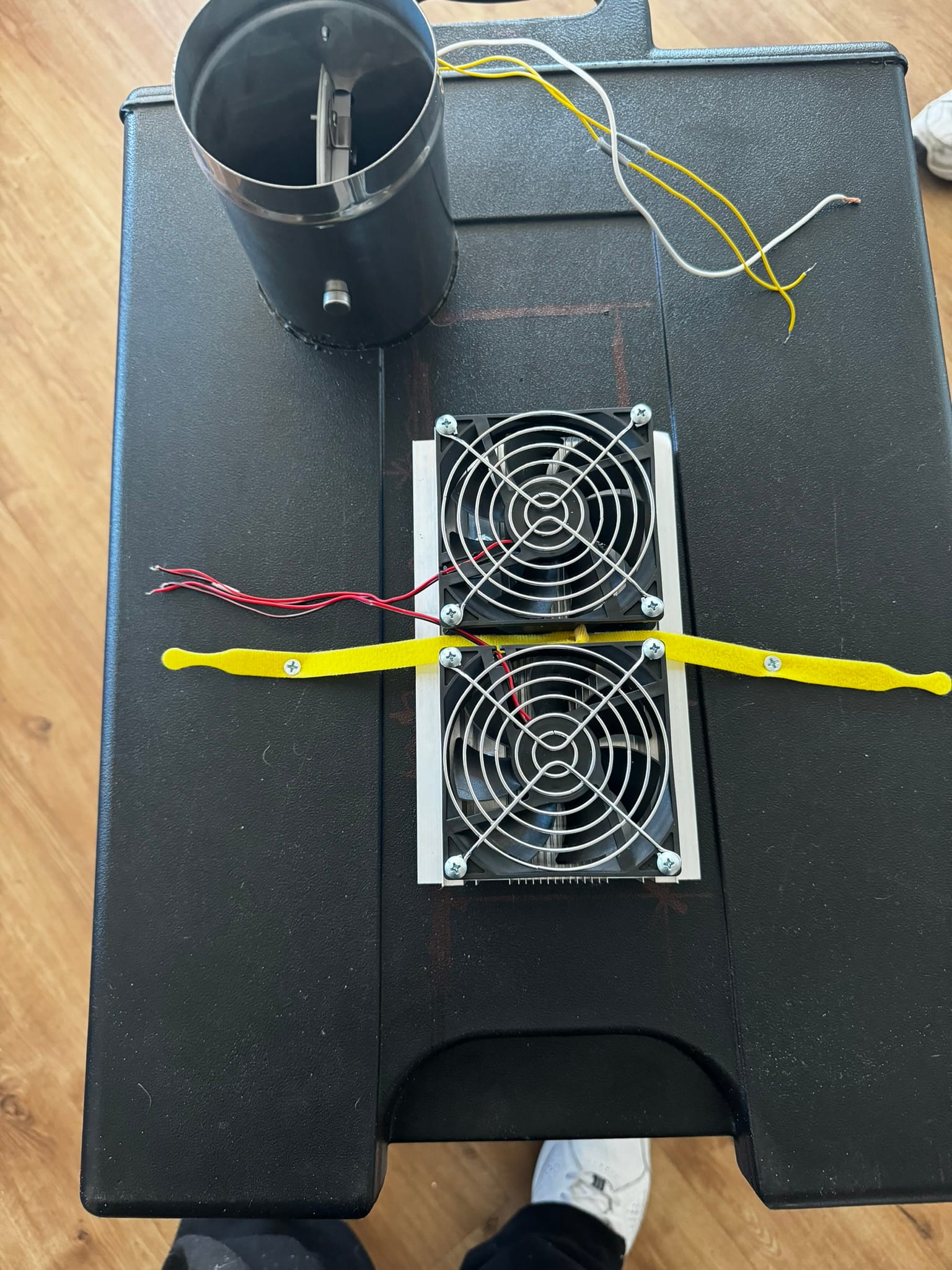
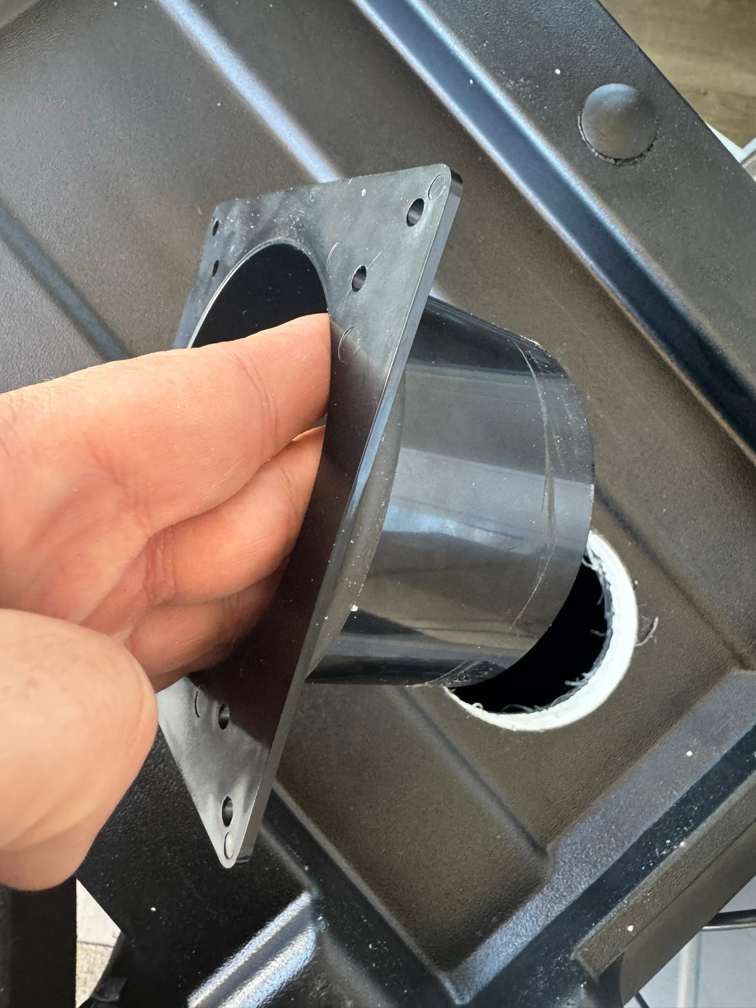
On the bottom of the box, use a ducting shrowd to attach the 120mm fan
Your box is basically done now.
Now you need to build the control box and run the wires. This part is a bit arduous; patience is the key.
Note: I am using a servo driver as a PWM controller, but it might be overkill. I might modify this in the future to use PWM straight from the GPIO pins.
Note: You will need to solder a GPIO header onto your pi.
- I used a shoe box, but I will modify this in the future to use proper project box
- In the shoebox I have
- 5 mosfets (Note: I will likely move these to the container)
- 12v power supply
- 5v buck converter
- Rasberry pi with servo/pwm hat
- LCD Screen
- Three momentary switches (buttons) and a power switch
- Now you just need to wire everything together. I will add details and photos as possible in the future. For now, I will just give it to you raw. If you don't understand electricity, you should probably wait for the detailed version.
- 12vdc -> 5vdc buck converter
- 12v+ -> All 12v components
- 12v- -> Pi GND
- 5vdc -> LCD screen
- 5vdc -> Pi 5vdc
- PWM 0 -> Outake fan
- PWM 1 -> Circulation fan
- PWM 2 -> 220Ω resistor -> Mosfet Gate
- Moseft 12v- -> Peltier cooler cores (1 PWM signal for both cores) 12v-
- I2C (sda+sdl) -> LCD, Sht30, Bme280
- GPIO 17, 27, 22 -> 220Ω resistors -> Up, Down, Enter Button
- Add 10kΩ pull down resistors to ground
- GPIO 24 -> 220Ω resistor -> Mosfet Gate
- Mosfet 12v- -> All peltier fans (hot and cold sinks) 12v-
- GPIO 25 -> 220Ω resistor -> Mosfet Gate
- Mosfet 12v- -> outtake fan 12v-
- GPIO 20 -> 220Ω resistor -> Mosfet gate
- Mosfet 12v- -> Damper open
- GPIO 21 -> 220Ω resistor -> Mosfet gate
- Mosfet 12v- -> Damper close
